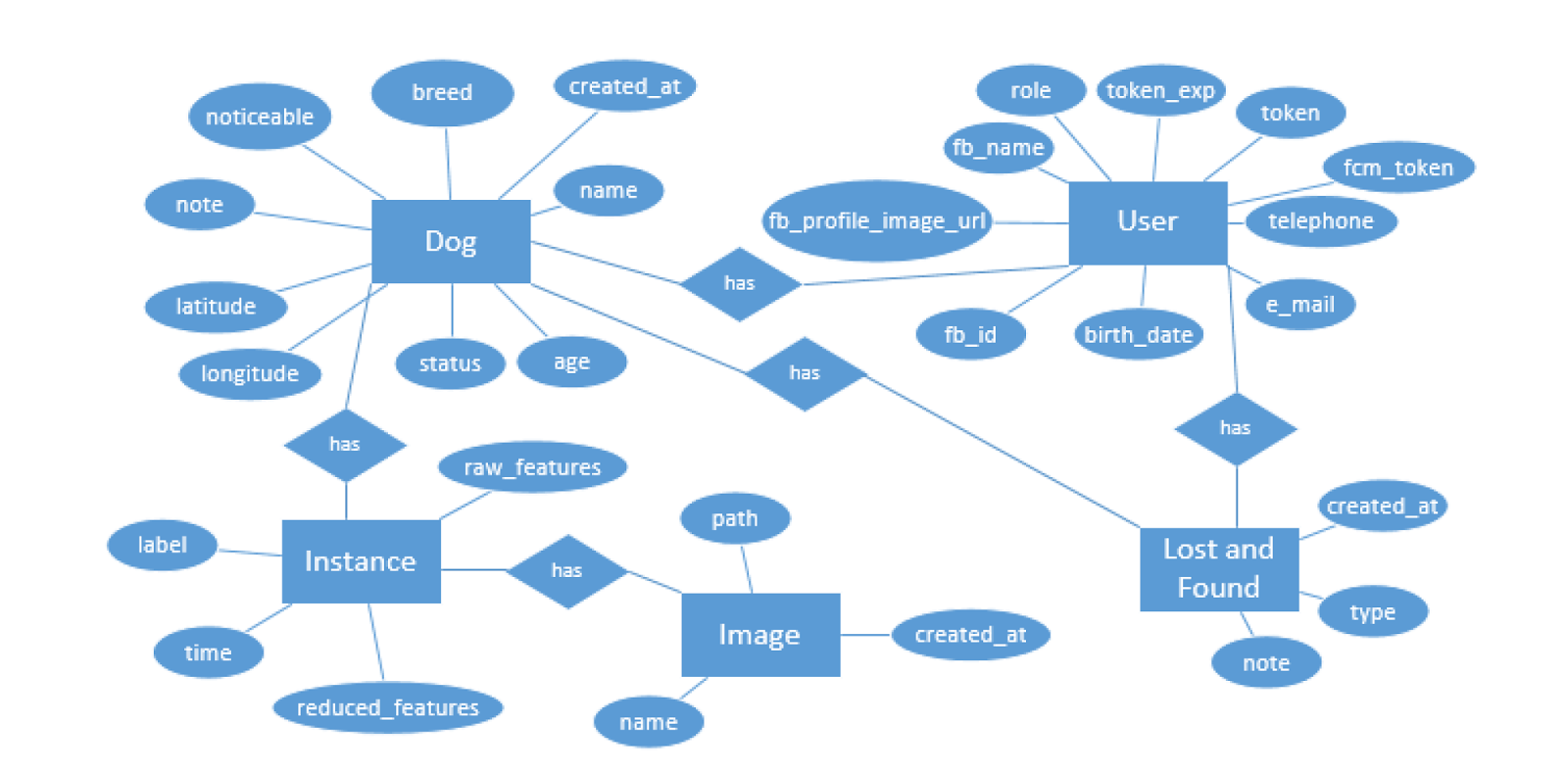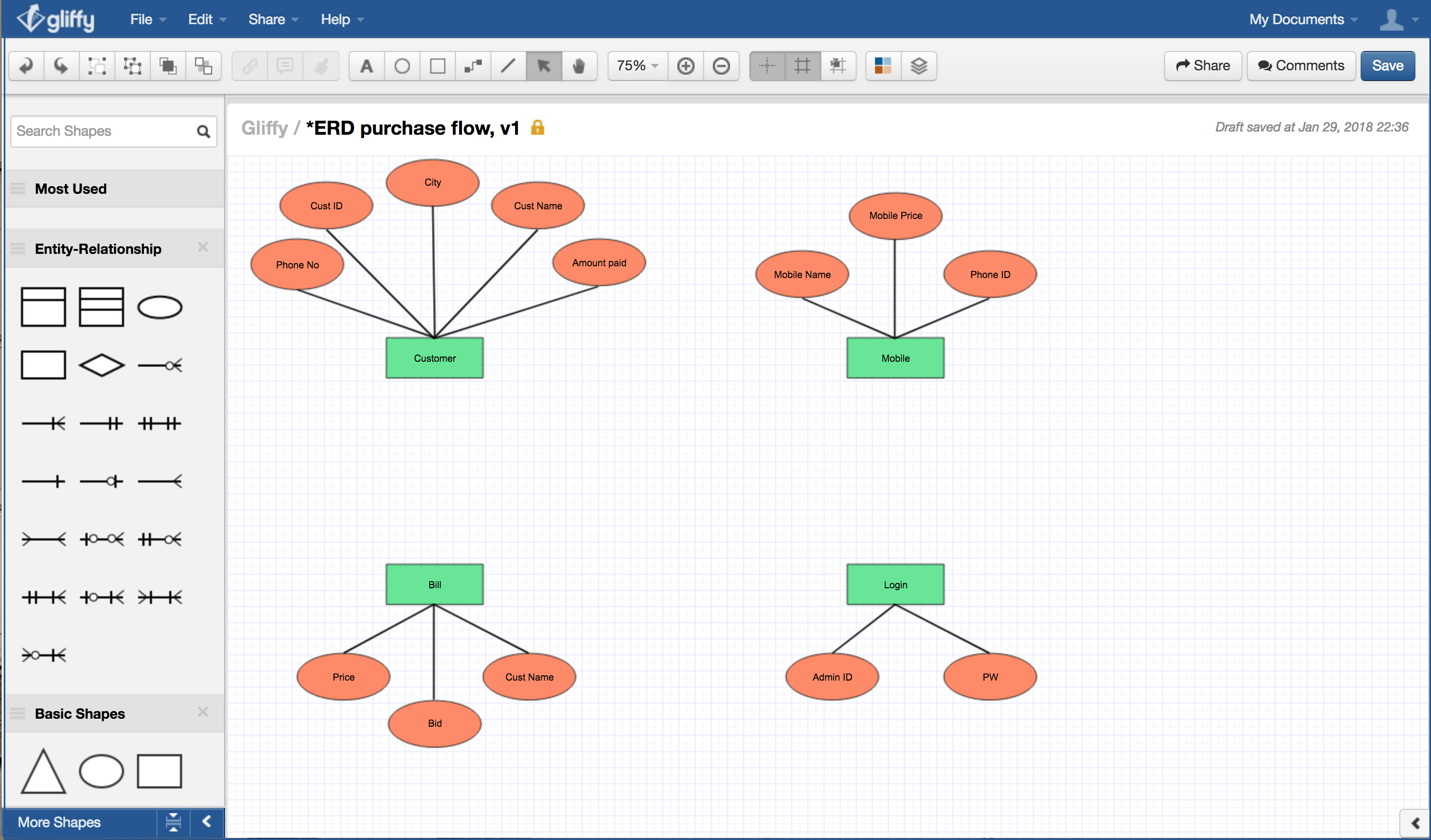

The conceptual data modeling phase in general is independent of a DBMS. During this process, the top two phases are concerned with the information content of the database, while the last two phases are concerned with the implementation of the database on some commercial DBMS.ĭuring the conceptual data modeling phase, data requirements are expressed through an ERD. Since data has become a vital corporate resource (Adelman et al., 2005 Dyche, 2000 Liataud & Hammond, 2001), good data models can make a significant contribution to an organization’s future success.ĭata modeling is performed during the initial phases of the database development process (also referred as database life cycle) as shown in Figure 1(Mannino, 2006 Rob & Coronel, 2006). It provides a means to analyze business requirements so as to standardize organizational vocabulary, enforce business rules, and ensure adequate data quality. Data modeling is an essential component of database design and development. 1.0 IntroductionĮntity relationship diagram (ERD) is one of the most widely used technique for data modeling. The paper concludes with a set of guidelines to refine an ERD to include normalization principles. Application of normalization during ERD development allows for more robust requirement analysis. This paper suggests inclusion of normalization during ERD development. An ERD developed during the conceptual data modeling phase of the database development process is generally transformed and enhanced through normalization principles during the logical database design phase.
Er diagram staruml driver#
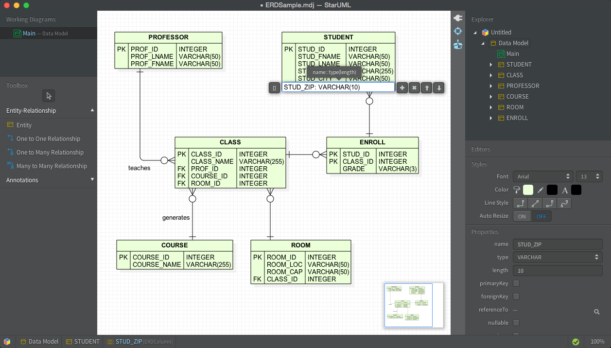
Create entity Driver from Bus with a one-to-one relationship.Entity relationship diagram (ERD) is one of the most widely used technique for data modeling. Create the following columns in Bus:Ī bus is driven by a bus driver. Create an entity Bus from Schedule, with an one-to-one relationship. Select One-to-Many Relationship -> Entity to create entity Schedule.Ĭreate the following columns in Schedule:Ī schedule is handled by a bus. Press and drag out the Resource Catalog icon. Create an entity Schedule from Route with a one-to-many relationship. Name the new entity Stop, You can see that a linked entity Route_Stop is automatically created in between Route and Stop, with foreign key added. Release the mouse button and select Many-to-Many Relationship -> Entity from Resource Catalog. Drag out the Resource Catalog icon at top right. Place the mouse pointer over the Route entity. Therefore, there is a many-to-many relationship between Route and Stop. A bus route has many bus stops, while a stop can be shared by many routes. Enter fare : float and press Enter, then Esc to create another column.Varchar is the column type and 10 is the length.

Note that the + sign means that the column is a primary key.

Create a new project by selecting Project > New from the application toolbar.


 0 kommentar(er)
